The project continues. Today, I needed to relinquish the doorframe I had been using.. so I got a chunk of scrap lumber and have used that as a base. The motors are now mounted 48" apart, with the lines run over a pair of eyehooks to help keep things aligned. Above you can see the finished device leaning against a wall and outside on the grass.. along with a closeup of the motor/hooks, and a shot of it mounted on the wall above my desk. In addition, I mounted a cheap picture frame to use as a dry-erase surface as well as am using a dry-erase marker, it's a lot easier than changing paper over and over as I test various ideas.
The first test of the Frankenbotic Thinganator... surprisingly, it worked the FIRST time!
Here is the code for this alpha test.. mainly to show basic operation. The next steps include developing the math and functions for x,y location.. translating coordinates to tension lengths will require a little bit of math.
#include <Stepper.h> #define STEPS 48 Stepper stepper1(STEPS, 2,3);
Stepper stepper2(STEPS, 4,5); void setup()
{
// set the speed of the motor to 30 RPMs
stepper1.setSpeed(30);
stepper2.setSpeed(30);
} void loop()
{ for (int k=4; k>0; k=k-1) {
stepper1.step(10);
stepper2.step(10);
for (int j=3; j>0; j=j-1) {
for (int i=50; i>0; i=i-5) {
stepper1.step(i);
delay(0);
stepper2.step(i);
delay(0);
stepper1.step(0-i);
delay(0);
stepper2.step(0-i);
delay(0);
};
};
};
while (true) { }; // wait forever.
}
Two small steppers salvaged from trash printers operate the plotter, by using gravity as the third vector we can locate the pen anywhere on the drawing surface by varying the length of the lines it is suspended by. This design is also called a Wall Plotter or Whiteboard Plotter.
Spools for the line were made by using Super Glue to hold together a washer on each side of a nut, then superglued to the small gears that were present on the stepper motor shafts. A card table was stood on a folding chair to make a drawing surface.. since I built this in a doorway, there's no immediate surface for the plotter to work on. If wall-mounted, the wall serves as the plotting surface.
Also, since the "easel" isn't exactly vertical, a bit of inaccuracy and jerkiness is caused-- but again, this is just an alpha test of a prototype.. final versions will account for and eliminate this problem.
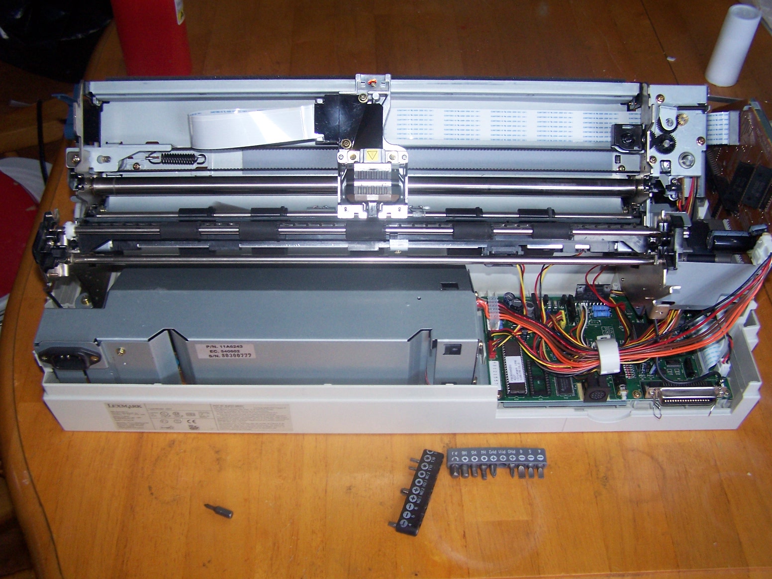
Step One: A trip to the local dump and a computer repair shop. Both free, got one older dot matrix
Lexmark and a newer inkjet Dell printers. Physical teardown took approximately two hours including
torch desoldering of relevant ICs. Except for a handful of potentially useful-looking hardware and screws
for the bins, the plastic and metal carcasses of the printers are then disposed of.
Teardown of the Lexmark gives us several stepper motors, ranging from small low-torque ones, all the
way to a NEMA 23 and one other high-power stepper motor. The Dell inkjet gives up a nice standard DC motor, as well as another mid-power stepper motor.
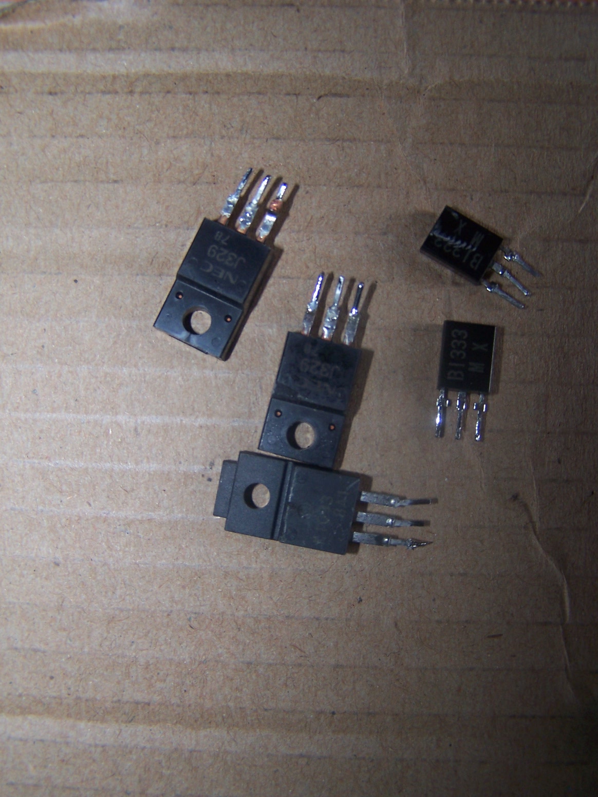
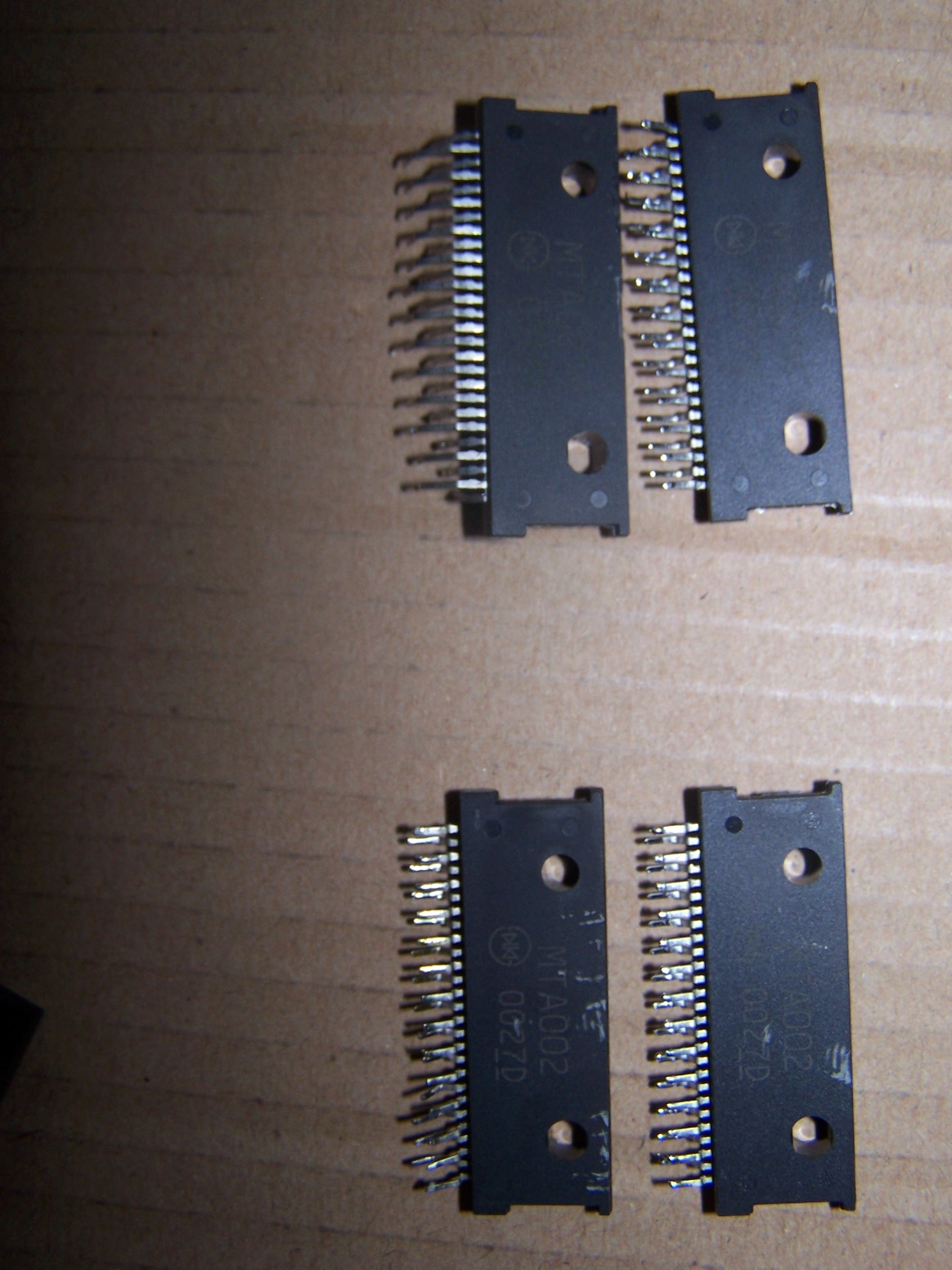
In addition to the motors themselves, a quick pass with a desoldering torch and we can reclaim the
driver IC's, a few power transistors, a few Darlington arrays, and some other miscellaneous
void loop() {

  for (int x=3; x<112; x=x+16) {

    for (int y=32; y<40; y=y+16) {

      s1=analogRead(0);

      TV.draw_rect(x,y,sz,sz,1,1);

      TV.delay_frame(2);

      s2=analogRead(0);

      TV.draw_rect(x-2,y-2,sz+5,sz+5,0,0);

      if (abs(s2-s1)>10) {

      TV.draw_rect(x-2,y-2,sz+5,sz+5,1,0);

      TV.delay_frame(5);

      };

    };

  };

 }
Virtually any light sensor will work, as long as it can provide an output that can be handled by the ATMEGA328's Analog to Digital Converter. For the simplest form, a CDS photocell simply connected to +5v on one side and the Analog 0 input pin on the Arduino on the other may suffice.
To increase sensitivity or adjust response, a simple voltage divider can be created by adding a variable resistance between Analog 0 and Ground with the above sensor.
So, I've got a few things coming up that require a portable, adjustable, high-power floodlight system for photography use. A wander around Home Depot, and for under $70, I was able to assemble a very workable Halogen flood rig using four 300W halogen bulbs in two heads, with linear faders, including reasonable-duty tripod.
Home Depot sells a two-head, four bulb halogen floodlight with tripod for $45. Each head has two switches on the back to switch the individual bulbs in the head. Add in a 4" square wiring box ($1), and two standard dimmer switches ($10 ea), and you have a very powerful, adjustable flood for under $70.
Sure, it's not the most complex thing ever.. however, it is EXTREMELY useful and just about the cheapest solution I could come up on short notice. 1200 Watts (all on, full power) of Halogen light is simply blinding, and should provide plenty for full-length shots. Not shown (but coming) is PVC pipe counterbalanced boom attached to the tripod with a 250W Halogen flood, for providing downlighting. The halogen flood cost $13, and a 10' run of 1 1/4" PVC pipe cost $3.50... and another $2 in a couple of carriage bolts.