Last time, we fiddled with the Arduino, exploring the basics of what we need to do- essentially, open and close a switch in a sequenced and time-precise manner. This time, we're going to take the finished prototype, write the first version of the software, and give it a try.
To begin, the circuit we'll be using is very simple- a single resistor and an optical isolator to protect our equipment from damaging voltages. The first version has no interface to the user- you plug it into the camera, set the camera to the aperture and focus you need, and turn on the Arduino. It will run through the program we write once, then put itself into an endless loop doing nothing until we remove power. Later I'll be putting this in a case of some sort, and adding at least a power switch. Until then, we'll simply connect the battery once everything else is in place. Not the most elegant solution, but I had no reasonable switches at the moment and we're only prototyping. Doing things like this is not really recommended- but if you are like me, you'll try to find a way to make do with what you have got.
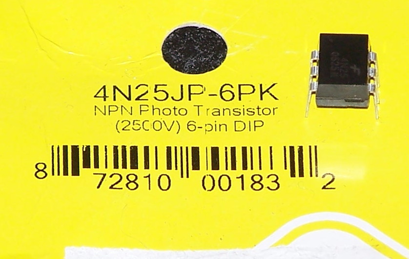


Assembled prototype, with 9v battery for power. The Arduino's onboard 5v regulator (seen just above the power plug in this photo) happily produces clean 5v for quite some time from a standard 9v battery. The tip and shield contacts from the 2.5mm plug go to the optoisolator output, which acts as a switch. Canon remote shutter releases are nothing more than pushbutton switches connected between these contacts. To make prototyping easier, the wires from the 2.5mm plug were soldered onto three breadboard header pins and then secured together with a dab of epoxy for a bit of mechanical strength.
The code we'll use this time includes reporting of the trigger's status via the serial port, mainly for troubleshooting purposes- however, since the overhead is small, I try to include some status outputs from my code to both illustrate it's function as well as potentially provide usable information. A running status feed is sometimes very useful to have.. and also allows others to use those feeds for their own purposes. Making ways for others to piggyback on your work is always a good idea in my book.
int shotcount = 9; // Hardcode for 9 shots for now
int shutterPin = 5; //
long mintime = 4; // Try for 1/250sec min exposure
long delaytime;
void setup()
{
pinMode(shutterPin, OUTPUT);
Serial.begin(9600); // setup to communicate by serial
}
void loop()
{
Serial.print("Sequence: "); // provide summary info by serial
Serial.print(shotcount);
Serial.print(" shots, minimum ");
Serial.print(mintime);
Serial.println(" ms.");
int i=0;
delaytime=mintime;
while (i < shotcount) {
Serial.print("shot duration: "); // dump shot info to serial
Serial.print(delaytime);
Serial.println(" ms.");
digitalWrite(shutterPin, HIGH); // open the shutter
delay(delaytime); // wait for the exposure time
digitalWrite(shutterPin, LOW); // close the shutter
delay(2000); // wait two seconds for camera
delaytime=delaytime*2; // double duration for 1eV step
i=i+1; // go on to the next shot
};
Serial.println("Sequence Complete!");
while (1) {}; // Wait forever
}
When we upload the program to the Arduino and open the Serial Monitor (which displays the information the Arduino sends on the serial port), we get the following output over a period of about twenty seconds total. Power cycling or pressing the Reset button on the Arduino produces the same. If we assume the remote shutter hardware works properly, the results should be a series of nine photos, starting with a 1/250sec exposure and finishing with a 1 second exposure (1.024 seconds actually).
Sequence: 9 shots, minimum 4 ms.
shot duration: 4 ms.
shot duration: 8 ms.
shot duration: 16 ms.
shot duration: 32 ms.
shot duration: 64 ms.
shot duration: 128 ms.
shot duration: 256 ms.
shot duration: 512 ms.
shot duration: 1024 ms.
Sequence Complete!
A few remarks: First that the minimum exposure of 4ms may not fully work. This is because it's been reported the fastest speed one can trigger on the shutter release is around 5ms which is 1/200sec. This minimum therefore will either work to produce a 1/250sec exposure, or as close as we'll get. As I understand this may be able to be reduced by using "Mirror Lock Up" function on the camera- but we'll worry about camera settings in a little while, after we get the trigger working. Additionally, since I am simply doubling the exposure time at each interval, we're not getting "true" standard exposure times.. but not too far off to make them unusable. In terms of exposure, there's little difference between a second and 1.024 seconds.
This all being said, when plugged into the shutter release port on the side of my Canon Rebel XT and powered up, the camera began dutifully clicking away under the command of the little Arduino.
Hi,
ReplyDeleteI was making the same rig. I have kind of technical question. Since, I've been trying to set it up, the same way you did - I couldn't. I'm even using the same camera, same optoisolator. I was connecting wire 2 and 3 (those two which are actually causing shoot). As long as I didn't include resistor (10k) between pin 4 and 6 of 4n25 I didn't manage to make it work. My question is.. did you have any similar issues? I've seen similar setups, and anyone was mentioning this problem.. so, any feedback from you would be appreciated.
Michal
Quite confused to your question.. 10k resistor?
ReplyDelete